FUNCTIONAL OVERVIEW
The PHIBER FWF Manifold is a proprietary plumbing configuration that transforms a raw water network to include safe and correct freshwater flushing as a primary function. It uses only physics to operate, responding to changes in line pressure on both the freshwater and raw water circuits.
There are two modes of operation for the Manifold:
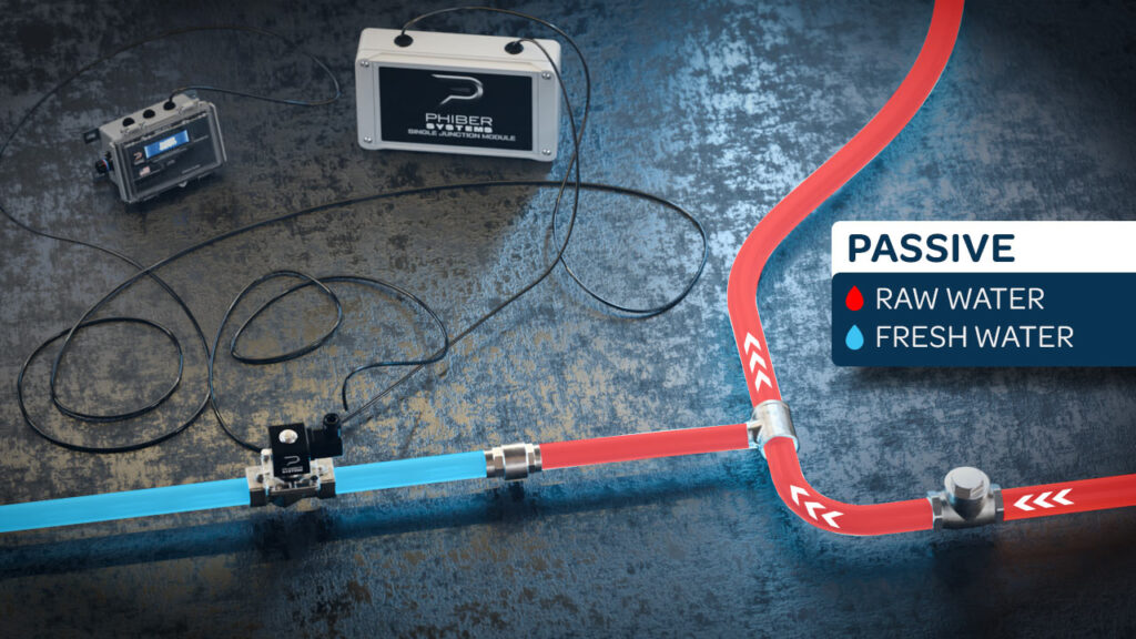
- PASSIVE – the Manifold responds to suction
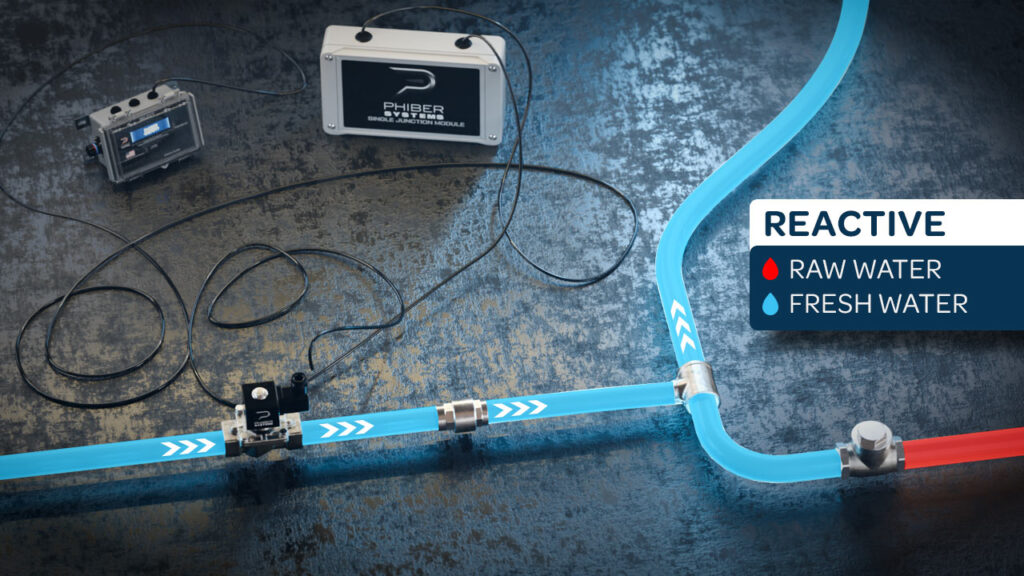
- REACTIVE – the Manifold responds to pressure
When a Manifold is correctly configured and properly installed between a vessel’s freshwater and raw water networks, its native operating state is passive, which means that the raw water network functions normally and seawater flows freely in direct response to the demands (suction) of the raw water pump.
During a freshwater flush cycle, the Primary FWF Gate receives a signal from the PHIBER Control Module to engage, allowing pressurized fresh water to flow into the Manifold. The Manifold’s operating state becomes reactive, and it directs the incoming flow of fresh water into and through the raw water network until the flushing cycle is complete.
The design of the FWF Manifold preserves the integrity of both freshwater and raw water systems. It can never starve the raw water network of critical water flow, and a true hydrostatic lock ensures that raw water NEVER contaminates the freshwater network.
There are two variations of the Manifold design:
- “INBOARD” FWF Manifold
- For complex raw water networks such as on diesel propulsion engines, generators, and more.
- For raw water circuits that must be flushed while they are active and the raw water pump is operating, preserving (pickling) the circuit with fresh water upon shutdown.
- “Overboard” FWF Manifold
- For simple raw water circuits such as on outboard engines, Vessel Gyroscopic Stabilization, desalination, refrigeration, climate control systems, and more.
- For raw water circuits that must be flushed while they are inactive and the raw water pump is off, flushing water through the circuit
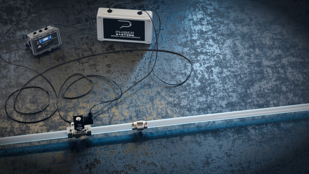
All PHIBER components for the FWF Manifold are constructed using the highest quality 316 Stainless Steel. This allows universal installation into any alloys used in marine systems.

Any PHIBER FWF Manifold must be correctly sized to maintain adequate water flow through both the fresh and raw water networks at all times, whether during normal operation or during the flushing process.
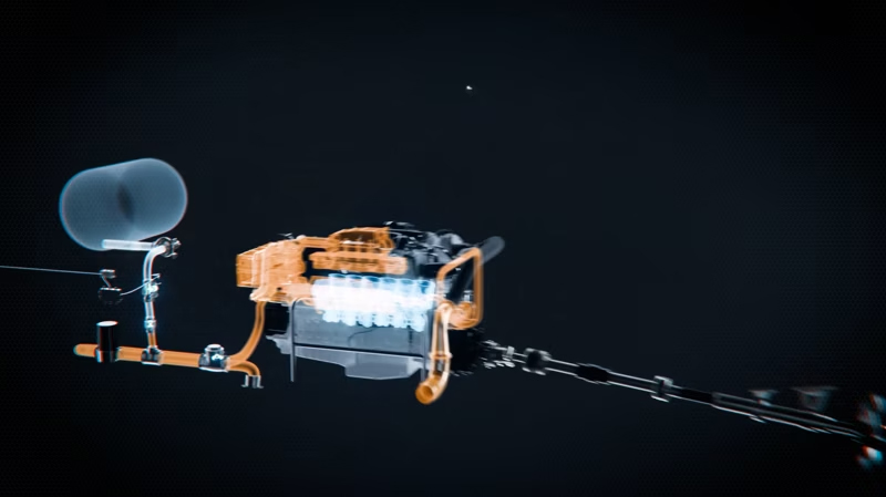
INBOARD MANIFOLD – INNOVATIVE ENGINEERING
The INBOARD FWF Manifold is comprised of FOUR unique components that operate in concert during the FWF process:
- Primary FWF Gate
- Fresh Water Spring Check
- Raw Water Swing Check
- Balancing Tee
As the introduction of pressurized fresh water displaces the flow of seawater that is sucked into an INBOARD raw water network, the water pressure in the Manifold rises. The strategic orientation of the INBOARD Manifold components ensures the flow of fresh water into and through the raw water circuit, flushing it until the flushing cycle stops, preserving (pickling) the raw water network with fresh water.
OVERBOARD MANIFOLD – CLEVER DESIGN
The OVERBOARD FWF Manifold is comprised of TWO unique components that operate in concert during the FWF process:
- Primary FWF Gate
- Fresh Water Spring Check
In an OVERBOARD Manifold, the introduction of pressurized fresh water is used to perform a simple flush of the raw water network. Flushing water is typically pushed through the network and then discharged overboard or drained via gravity out of the raw water circuit.
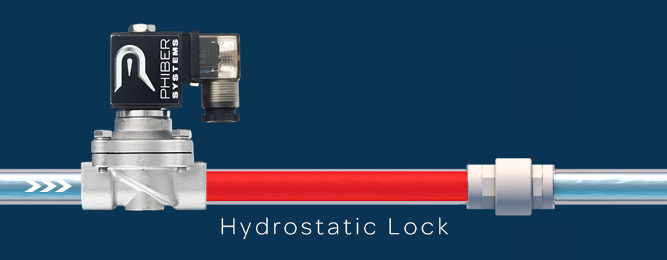
In a PHIBER freshwater feed circuit, water will only flow in one direction, so when the water conduit is filled with water and both ends of the conduit are mechanically closed, the water becomes trapped, and the flow will obviously stop.
Water is not compressible, nor can it be stretched, and a condition called “hydrostatic lock” occurs when a spring-loaded check valve and a gate valve are used at two locations to stop the flow of water and trap it between them.
In a hydrostatic lock, any suction on the “downstream” side of the check valve has zero effect on the spring check valve because the trapped water cannot stretch, so it cannot be “pulled” open; and because the spring-loaded check valve only allows water to flow in one direction, it cannot be “pushed” open.
Only pressurized water passing through an open Primary Gate upstream of the check valve can cause the spring check valve to open, allowing the pressurized fresh water to resume flow.
